Hardware Preparation (Vue 2)
Opening the case
Use a small philips screwdriver to open the case. You will then need to solder a serial header onto the programming port, so that it looks like this:
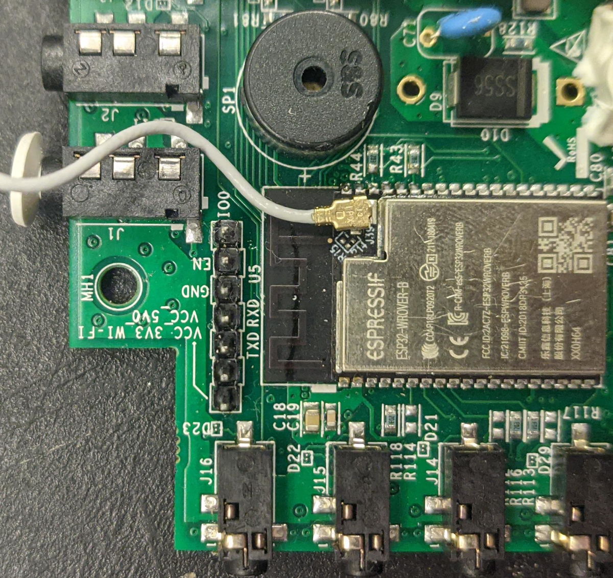
Connecting UART
Plug the USB adapter in. Connect the pins according to the following table:
| Adaptor | Vue |
|---|---|
| RX | RX |
| TX | TX |
| GND | GND |
Do not connect 5V or 3.3V at this time.
Connecting DTR/RTS
If your TTL adapter has both the DTR and RTS pins exposed, you can let it automatically reboot the board and put the chip into flash mode when necessary. Connect those now:
| Adaptor | Vue |
|---|---|
| DTR | IO0 |
| RTS | EN |
Using ground jumper
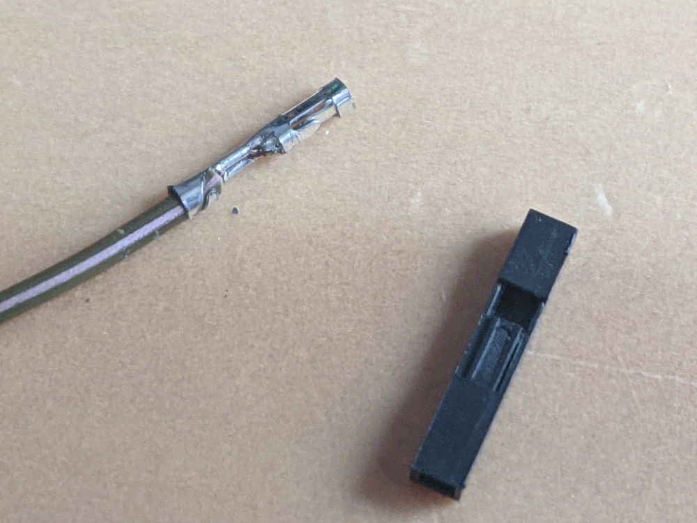
If your adaptor does not have a DTR and RTS pin, you can manufacture a ground jumper wire.
Pry the lever on one of the jumper cables up using a pencil or a needle or some other sharp thing. If your cables don't have a lever, cut one end of the cable & strip it using scissors or a knife.
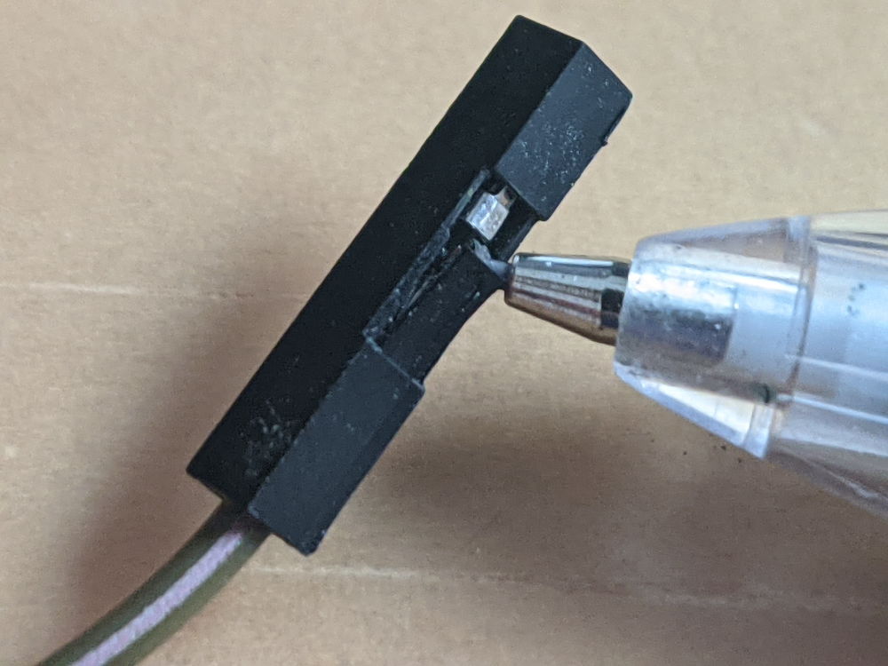
Plug in the unmodified end of the cable into the IO0 pin of the Emporia Vue 2, and tape down (or, less ideally, hold) the other end onto the shield
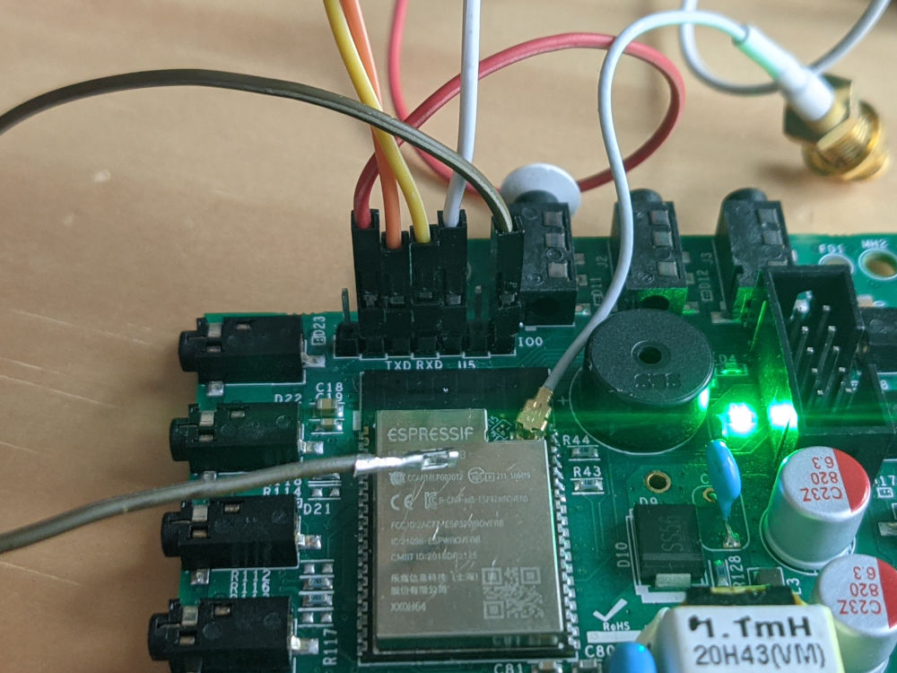
Connect power
Do not mix up 5V and 3V, or you will destroy your board.
Connect 5V on your UART adapter to the VCC_5V0 pin on the board.
Because you have either taped down IO0 to ground or are using the DTR/RTS pins, your board is now in bootloader mode, and you can now backup software off of it and load new software on.