Hardware Preparation (Vue 3)
Opening the case
Disassembly is fairly straightforward. Remove all the screws from the bottom, and possibly loosen the SMA connector a bit. Then you should be able to pop the two halves of the plastic case open, carefully with a pry tool or similar.
Connecting UART
Do not connect 5V or 3.3V at this time.
Once inside, there are five test point pads involved to flash the Vue 3:
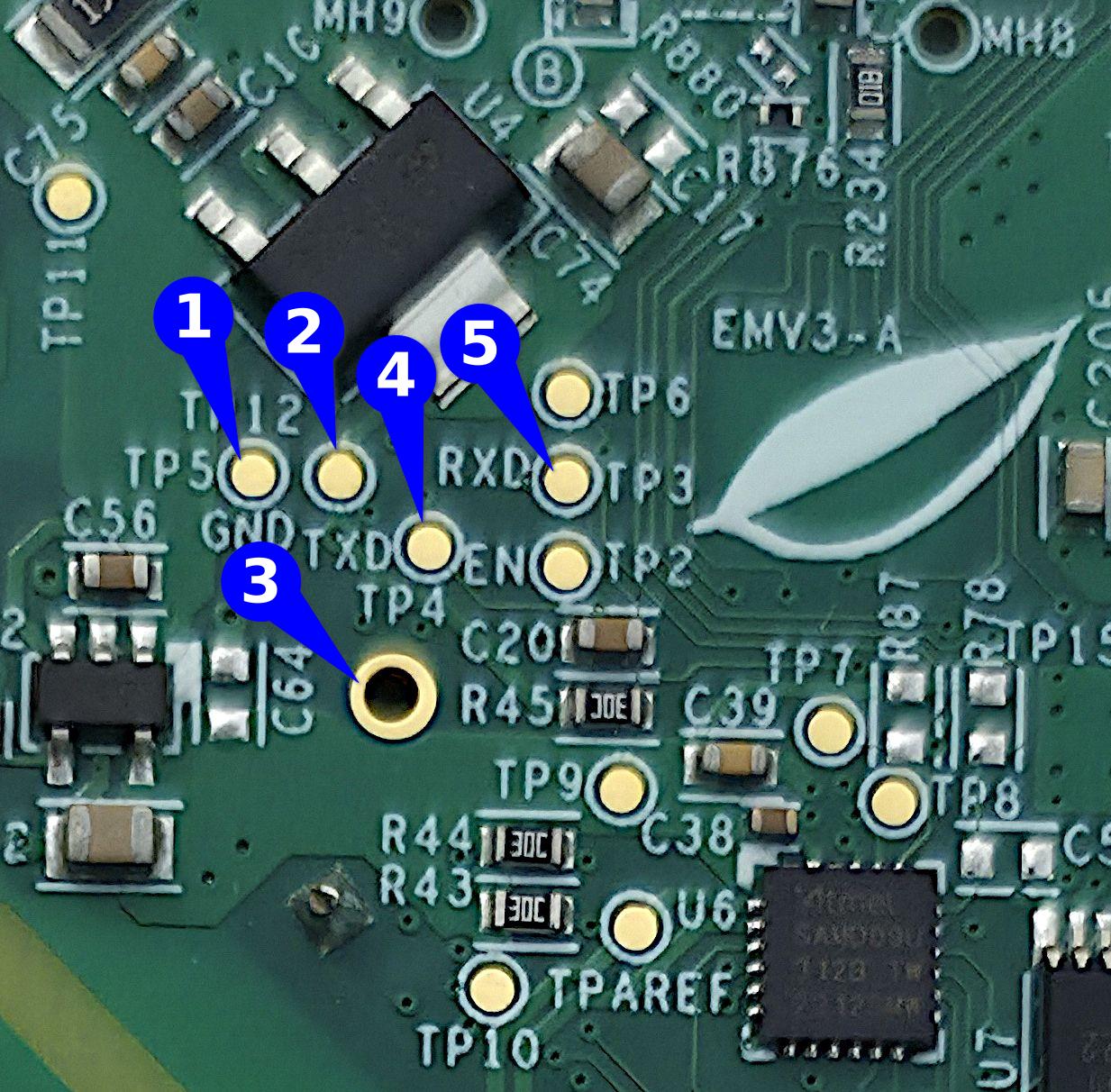
Using a BDM frame, a soldering iron, or something similar, connect the gold contacts on your board as follows:
| Label # | Connect to |
|---|---|
| 1 | GND |
| 2 | 3.3V |
| 3 | GND |
| 4 | your UART adaptor's TX pin |
| 5 | your UART adaptor's RX pin |
See the original thread for additional tips/instructions, or this set of tips on how to use a BDM frame together with aligator clips to make it easier.
The RX & TX pins can be confusing, even for people with lots of experience in this kind of thing. If your board powers up but is not being discovered, it's often worth to try and fix it by flipping the RX & TX.
Connect power
Do not mix up 5V and 3V, or you will destroy your board.
All that's left to enter bootloader mode is to power the ESP32 via the 3.3V test point (labeled in the picture, next to GND/TP5 on the board).
Because you have either taped down IO0 to ground or are using the DTR/RTS pins, your board is now in bootloader mode, and you can now backup software off of it and load new software on.